
Blog
Wood Router Bits: Design & Manufacturing of Jointer Bits

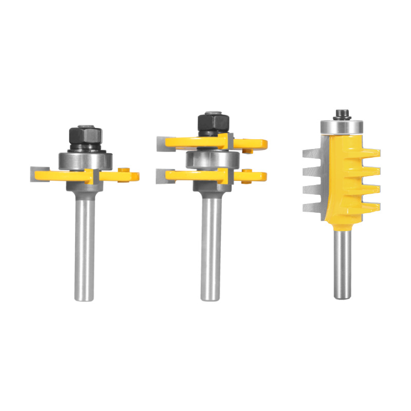
A jointer bit is the core cutter for tenon and mortise joints in woodworking. A fine carbide tool must balance three demands at once. These are a keen cutting edge, a reliable brazed joint, tight accuracy, and safe balance. From blade geometry to welding, from profile grinding to assembly, every step sets cut quality. In this guide we show how wood router bits of the jointer family are designed and built.
Three Structural Types
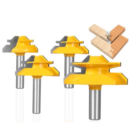
Jointer bits fall into three build styles. The integral type fuses the cutting edge and body as one piece. It is simple and versatile for cabinets, door frames, and flooring. The semi-integral type fixes the curved profile to the shank. It uses a replaceable round insert for the T-section, suiting busier shops. The split type is the most flexible of the three. A shank, profile blade, slot blade, bearing, spacers, and nut let you swap blades. You can cut two joint forms with one tool. This saves carbide and steel while lowering total cost.
Key Design Parameters
Geometry drives the performance of every carbide jointer bit. By extension, it shapes the wood router bits you trust on the table. The rake angle is set at 12° to 15°. It is kept as large as weld strength allows for a sharper bite. The clearance angle sits at 15° to 20°. It stays small enough to avoid burn yet strong at the tip. A side clearance of 4° to 6° and a relief near 8° help heavy cuts. Blade extension also matters. Radial standout is 1 to 1.5 mm and axial standout about 1 mm. The wheel reaches the edge without hitting the body, and the carbide keeps solid support. The machined axial size runs 0.05 to 0.08 mm under design, then shims fine-tune it.
Material Selection
Each part of these wood router bits earns its material. The body uses 45# steel or 40Cr, heat-treated to 35–42 HRC. It is sandblasted or painted for protection. The cutting edge is YG8, K10, or K20 carbide at 2 mm thick. It reaches at least 89 HRA for wear resistance. The bearing is a quiet, long-life high-speed type, commonly the 608. Crucially, the blade-to-body thickness ratio sets the welding stress. Therefore, it is controlled rather than left to chance.
The Welding Process
Brazing is where many tools fail. Carbide’s expansion coefficient is only about half that of steel. As a result, cooling after a hot braze leaves huge internal stress. Ordinary solder also wets carbide poorly, inviting delamination under impact. Four factors keep the joint sound. First, control the brazing temperature. Second, choose solder strength and elasticity; silver-based solders absorb stress. Third, watch the weld thickness. Fourth, manage the carbide-to-steel thickness ratio. After brazing, inspect for porosity and cracks. Apply a stress-relief heat treatment to prevent delayed cracking. Re-braze only when necessary, because repeated heating weakens carbide. A good joint fails in the blade or base during shear testing, never at the seam.
Production Workflow
The shaft route is cut, turn, mill flat, heat treat, thread, blacken, then grind. The blade route is cut, turn, mill slot, deburr, weld, blast, ream, and edge-grind. Profile blades are finished on a copy grinder; slot blades use a standard grinder. The formers that guide profile grinding carry a 0.4 to 0.5 mm allowance. They are cut from 2 mm steel plate, while slot-blade carbide stands about 8.5 mm high. Greener lines add fume extraction, water-based paints, and coolant recycling. Every batch of carbide jointer bits follows this same disciplined chain from blank to box.
Grinding and Inspection
Grinding wood router bits demands tight control because carbide is hard and brittle. Rough passes use a green silicon-carbide or diamond wheel at 46–60 grit. They run at high concentration, a soft wheel, and 10 to 12 m/s. Each pass removes no more than 0.04 mm. Finishing uses 80–100 grit diamond at 75–100% concentration. It uses a tighter wheel and removes no more than 0.03 mm per pass. Outgoing checks demand no cracks, burrs, or rust and a full weld. Radial runout stays at or below 0.05 mm and face runout at or below 0.03 mm. The profile-to-gauge gap stays at or below 0.1 mm. Surface finish reaches Ra 1.6 to 0.8 µm. Balance is no worse than G6.3, and the maximum speed is at least 12,000 rpm. Anti-loosening screws and a salt-spray rating of 9 or above complete the spec.
Assembly and Debugging
Final assembly is done by experienced technicians. They verify the actual joint fit and keep a wood sample with the tool. They confirm weld security so nothing shifts in cut. Axial and radial positions are set precisely so parts stay interchangeable. Both blade faces are plane-ground, with shim compensation for any deviation. Every tool is marked with maker, model, and maximum speed. For example, a three-flute T-jointer among modern wood router bits spaces its teeth 120° apart.
Conclusion
From integral to modular, from welding to profile grinding, building carbide jointer bits is a precision system. Each angle chosen, each process controlled, and each check passed shapes how the tool cuts. With CNC curve grinders, ultra-fine carbide, and cleaner process lines, these bits keep improving. They move toward higher accuracy, longer life, and lower cost for every workshop.