
Blog
Router Table Setup: Fence, Height and Zero Clearance

Most routing problems blamed on the cutter are really problems with the bench. In fact, a careless router table setup adds error to every single pass. Moreover, that error grows with the size of the part.
This article covers the four things that matter most. They are the table surface, the fence, the bit height and the insert ring. Then it gives you a tuning routine to repeat.
Start With a Flat, Rigid Surface
A good router table setup begins with the surface itself. The table must be flat and stiff, because any sag tilts the workpiece. Therefore, support the top along its length and check it with a straightedge.
Next, check the insert plate. It must sit flush with the surrounding surface. A plate that stands proud will catch the work. On the other hand, a plate that sits low lets the work dip into the gap.
Because the plate is the weakest link, adjust its levelling screws often. In addition, avoid over-tightening the ring, which can bow a thin plate.
Router Fence Alignment: Square, Parallel, Solid
The router fence decides whether the work travels straight, so treat it as a precision surface. First, check that the two faces are coplanar. Second, check that the fence is parallel to any mitre slot.
A common fault is a fence that angles slightly toward the cutter at the outfeed side. As a result, the work pinches after the cut and the profile changes size along the part.
Therefore, set the outfeed face flush with the infeed face, then lock both ends. Moreover, use a straightedge across both faces to confirm the joint before you cut.
For heavy work, add a tall auxiliary face to the fence. Because it supports more of the workpiece, it reduces tipping and improves consistency.
Setting Bit Height and Depth
Height control needs a repeatable reference, so mark it or gauge it. A digital depth gauge is fast, and a setup block is just as reliable.
Measure from the table surface to the highest cutting edge, not to the shank. Therefore, confirm the reading against a test cut in scrap.
In addition, lock the height adjustment before cutting. Some lifts drift under vibration, and a small drift changes a groove depth across a long panel.
Because the cutter rises as it wears during a long run, check the height again halfway through a large batch.
Zero Clearance Inserts and Safety
A zero clearance insert is a ring with an opening just wide enough for the cutter. Consequently, the workpiece is supported right up to the cut.
That support matters most on narrow parts, because it stops them from dropping into the gap. Moreover, it reduces splintering at the exit edge.
Make your own inserts from MDF or plywood and keep a stack of them. Also, label each insert with the cutter it was made for, so you can swap it quickly.
Above all, never run a cut without a ring fitted. An open hole turns a small part into a projectile.
Router Table Setup: The Tuning Routine
Work through the same list whenever you change a cutter or set up a new job.
- Check the table and insert plate for flatness and flush fit.
- Verify that both fence faces are coplanar and locked.
- Set the bit height against a gauge and lock the lift.
- Fit a zero clearance insert sized for the cutter.
- Confirm the feed direction against cutter rotation.
- Fit featherboards and check the dust port.
- Cut a test piece from the same stock as the job.
After that, measure the test piece instead of looking at it. Numbers reveal small errors that your eye will forgive.
Test Cuts That Prove the Setup
A good router table setup is only proven by a measurable test cut. Therefore, cut a short sample and measure the profile with a caliper.
In addition, cut a second sample and compare the two. If they differ, the fence has moved or the work has lifted. As a result, you learn which part of the setup is unstable.
For moulding profiles, run a longer sample through in one continuous pass. In this way you expose any drift that a short piece would hide.
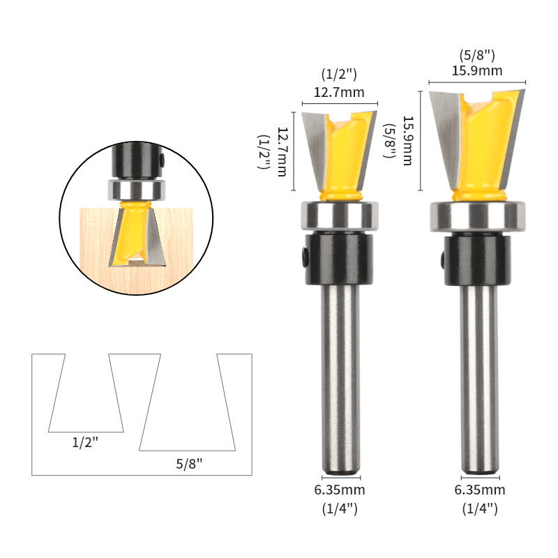
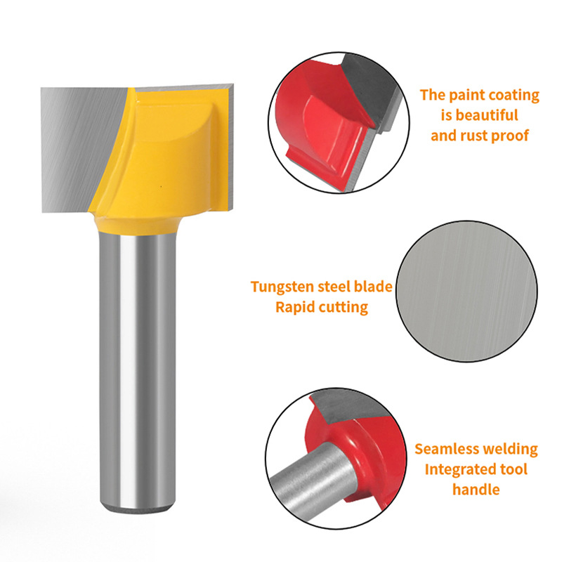
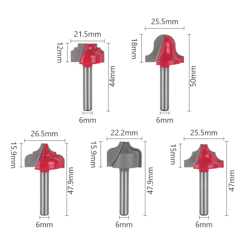
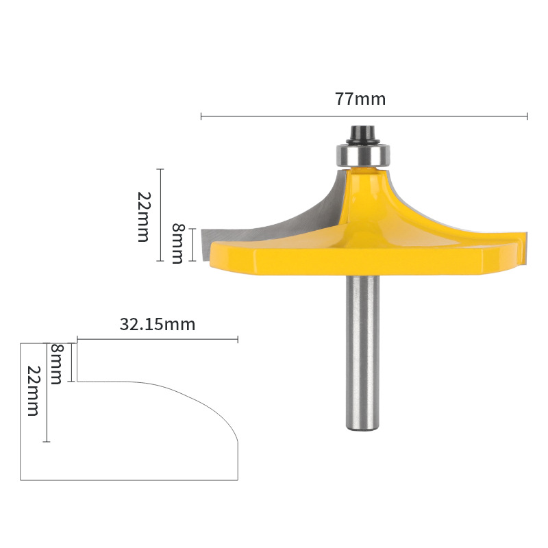
Reliable cutters make this testing worthwhile, because the tool stays consistent between parts. Our router bits are made to tight tolerances so the setup, not the cutter, controls the result.
Maintenance and Checkpoints
A good bench stays good only with small habits. First, clean the table after every job, because dried resin drags on the work. Second, wax the surface occasionally to lower friction.
Also, vacuum dust from the lift mechanism, and check the fence lock for wear. Furthermore, replace stripped screws before they fail mid-cut.
Finally, recheck fence alignment whenever you move the table. A bench that gets wheeled around needs a fresh check each time. Keep your cutter reference notes with a wider router bit collection list on the shop wall.
FAQ
How often should I check router table setup? Check it whenever you change a cutter, and recheck alignment after moving the table.
Is a zero clearance insert worth the effort? Yes. It is the cheapest upgrade for safety and edge quality.
Do I need a mitre slot? Not for every job. However, it helps for repeatable cross-grain work and jigs.
Set the bench first and the cutter second. A careful router table setup removes more error than any tool change you can make.