

Blog
Carbide Wood Joint Router Bits: In-depth Analysis of Design and Manufacturing Processes

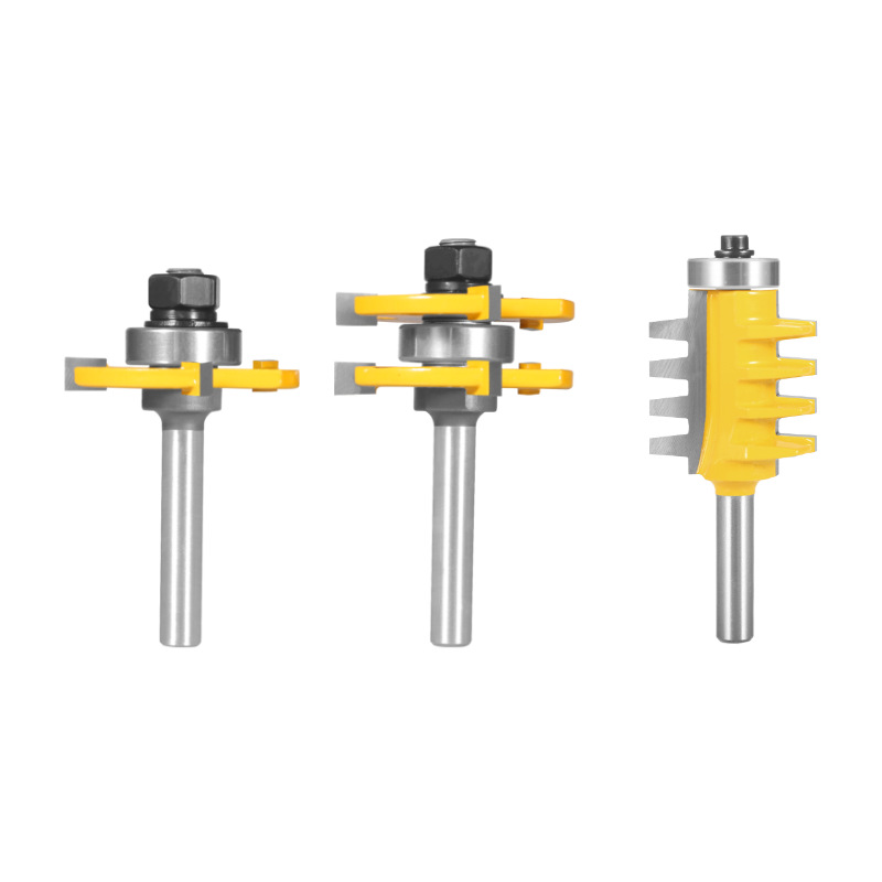
Wood joint router bits are core cutting tools used to create tenon and mortise connections between wood panels. Together with dado & jointer bits, they form the backbone of joinery work in cabinet and furniture production.
A premium carbide wood joint router bit must balance four things. Those are sharp cutting edges, reliable brazing, precise tolerances and dynamic balance safety.
Every stage matters, from blade geometry design and brazing operations to profile grinding and final assembly tuning. This guide covers the full technical workflow of carbide wood joint router bits. It runs through tool classification, design parameters, material selection, production processes, edge grinding and quality inspection. Along the way, we also look at how these cutters relate to dado & jointer bits in the wider joinery tool family.
Three Main Types of Wood Joint Router Bits
Carbide wood joint router bits fall into three structural categories, each suited to different production requirements.
Solid Wood Joint Router Bits
Cutting edges and the tool body form a single non-detachable unit. These bits are easy to machine and highly versatile. As a result, they serve many panel processing applications such as cabinets, door frames and flooring.
Common variants include box joint bits, T-type tenon bits and matched finger joint sets.
Semi-Solid Wood Joint Router Bits
The curved tenon profile is integrated with the shank and cannot be modified, while the T-type tenon section uses replaceable circular blades. This layout suits wood joinery manufacturers with diverse production demands.
Modular Wood Joint Router Bits
Modular bits are the most flexible configuration. A typical unit consists of a shank, forming blades, slotting blades, bearings, shims and locking nuts. Loosen the nut, and you can swap forming blade A for slotting blade B, so one tool machines two different workpiece profiles.
Key benefits: they save tungsten carbide and tool steel material, improve blade utilisation and reduce overall production costs.
Critical Design Parameters
Angle Parameters
| Parameter | Recommended Range | Design Notes |
|---|---|---|
| Rake angle | 12°–15° | Maximize the value while maintaining brazing strength for better sharpness; verify rake angle at the minimum cutting diameter |
| Clearance angle | 15°–20° | Keep the value low to avoid wood burning; excessive angles weaken the cutting tip |
| Side clearance angle | 4°–6° | Critical for deep-cutting tools; side blades tilt inward roughly 2° toward the centre |
| Cutting edge inclination angle | ~8° | Use inclined blades for long side edges under heavy cuts to stabilise machining |
Blade Protrusion and Axial Control
- Radial protrusion Ca: 1–1.5 mm
- Axial protrusion Cr: approximately 1 mm
The purpose is to prevent grinding wheel interference during sharpening. At the same time, the protrusion keeps optimal support strength behind the carbide blades.
Axial dimensions are machined 0.05–0.08 mm smaller than the nominal design size. Thin shims of 0.1 mm or 0.2 mm then compensate tolerances during assembly.
Common Angle Specifications for Finger Joint Bits
Finger joint profiles and dado & jointer bits both rely on the brazing fundamentals described later in this guide.
| Type | Critical Angles | Application |
|---|---|---|
| Tapered finger joint bit | Inclination angle 0°, taper angle 14°10′ | Finger joint panel production |
| 45° joint router bit | Bevel angle 45° | Handrails and decorative woodwork |
| 15° finger joint bit | Finger groove angle 15° | Panel finger joints |
| Helical finger joint bit | Helical tooth profile | Specialised finger joint applications |
Material Selection
| Component | Material | Hardness & Requirements |
|---|---|---|
| Tool body | 45 steel / 40Cr | Heat treated to 35–42 HRC, surface blast cleaned or painted |
| Cutting edge | YG8 / K10 / K20 | 89 HRA or higher, blade thickness 2 mm |
| Bearing | Premium high-speed bearing | Smooth rotation, low noise, long service life; 608 type widely used |
The thickness ratio between carbide blades and the steel tool body is a key brazing design parameter. Improper ratios easily trigger concentrated thermal stress and cracking.
Key Brazing Process Guidelines
⚠️ Two core challenges in brazing
- Cracking: tungsten carbide has a linear thermal expansion coefficient of 5–7 × 10⁻⁶ /°C, nearly half that of steel at 11–14 × 10⁻⁶ /°C. Huge internal stress therefore develops during cooling after high-temperature brazing.
- Debonding: ordinary filler metal wets carbide surfaces poorly, so blades may detach under cutting impact.
🔑 Four controlling factors for brazing
- Brazing temperature: excess heat amplifies thermal stress, while insufficient heat prevents proper filler metal flow.
- Filler metal strength and elastic deformation: select silver-based brazing alloys with good wetting capacity, and let slight weld seam deformation absorb stress.
- Weld seam thickness: too thin causes weak bonding, too thick increases residual stress, so precise control is required.
- Carbide-to-steel thickness ratio: optimised ratios reduce warping and cracking risk.
🔍 Post-brazing inspection and treatment
- Inspect weld seams for porosity and check workpieces for cracking.
- Apply suitable post-brazing heat treatment to relieve residual stress and prevent delayed cracking.
- Defective tools can be re-brazed, but limit repeated heating cycles, because multiple thermal cycles degrade carbide performance.
- Brazing strength verification: shear testing should produce failure in the blade or substrate rather than along the weld seam.
Performance gains from ultra-fine grain carbide: brazed joint strength improves by more than 20%, cutting edge hardness reaches HRA90 or higher, and tool service life increases by more than 30%.
Full Production Workflow
Shank Manufacturing Process
Raw material cutting → turning → milling flat sections → heat treatment (30–35 HRC) → thread rolling → black oxide finish → grinding.
Blade Manufacturing Process
Raw material cutting → turning → slot milling → deburring → brazing → sandblasting or painting → reaming → edge grinding → cleaning → assembly.
Forming blades are ground on profile grinding machines, while slotting blades can be processed on standard tool grinders.
Carbide Blade and Template Design
- Leave a 0.4–0.5 mm grinding allowance on carbide blades, oversized compared with the theoretical profile.
- The template contour matches the theoretical cutting edge profile, with a relief extension of about 10 mm at the edge to accommodate grinding wheel overtravel.
- Templates are laser cut from 2 mm steel plate.
- Standardised slotting carbide blades have a height of roughly 8.5 mm.
A small number of domestic manufacturers have developed semi-automatic and fully automatic CNC curve grinders. Those machines greatly boost precision and productivity.
Eco-Friendly Production Practices
- Welding fume extraction hoods paired with bag dust collection
- Water-based paint replacing solvent paint, with thermal curing
- Cutting fluid and waste residue separation, plus metal scrap recycling
- Recirculating cleaning fluid and compliant waste liquid disposal
Edge Grinding Technology
The grinding discipline below mirrors what good suppliers apply to dado & jointer bits on the same production line. Tungsten carbide is hard yet brittle, and its thermal conductivity is poor. Improper grinding therefore causes chipping and thermal burn easily. Control wheel selection and grinding parameters strictly.
| Item | Rough Grinding | Finish Grinding |
|---|---|---|
| Abrasive | Green silicon carbide / diamond | Diamond |
| Wheel grit | 46#–60# | 80#–100# |
| Diamond concentration | High concentration for strong cutting capacity | 75%–100% (medium concentration) |
| Wheel hardness | R2–R1 (soft grade) | R2–R1 |
| Wheel structure | 9–11 (open structure) | 6–7 (denser structure to retain profile) |
| Grinding speed | 10–12 m/s power feed | 15 m/s manual feed |
| Material removal per pass | 0.04 mm or less (46#–60#) | 0.03 mm or less (80#–100#) |
| Longitudinal feed rate | 1–1.5 m/min | 1–1.5 m/min |
Inspection and Factory Acceptance Standards
These acceptance rules apply equally to joint router bits and to dado & jointer bits built on the same equipment.
Visual inspection: no cracks, burrs or rust; full weld seams without cold joints or porosity; sharp cutting edges free of chipping or dull spots.
Geometric tolerances:
- Radial runout 0.05 mm or less
- End face runout 0.03 mm or less
- Gap between cutting profile and master gauge 0.1 mm or less
Surface roughness: Ra 1.6–0.8 µm. Dynamic balance: minimum G6.3 grade (GB/T 9239.11).
Safety specifications: maximum operating speed of 12,000 RPM or more, anti-loosening locking fasteners, and no red rust after salt spray testing with a rust resistance grade of Grade 9 or better.
3-Tooth T-Type Joint Router Bit Specification Reference (Q/YSGJ 002-2026)
| Model | Cutting Diameter | Shank Diameter | Overall Thickness | T-Tenon Width | T-Tenon Height | Corner Radius R |
|---|---|---|---|---|---|---|
| T-10-8 | 45 mm | 12 mm | 35 mm | 10 mm | 8 mm | 3 mm |
| T-12-10 | 50 mm | 12 mm | 40 mm | 12 mm | 10 mm | 4 mm |
| T-16-12 | 60 mm | 16 mm | 45 mm | 16 mm | 12 mm | 5 mm |
Three cutting teeth are evenly distributed, and the included angle between adjacent teeth is 120° with a tolerance of ±1°.
Assembly and Tuning Guidelines
- Assembly and tuning must be completed by experienced professional operators.
- Verify tenon mating quality, and keep a wood test sample packaged together with the tool.
- Inspect brazing integrity to ensure no loosening or shifting during cutting.
- Confirm precise axial and radial positioning, because all interchangeable parts must fit consistently.
- Both end faces of the blades require surface grinding, and thin shims compensate dimensional deviations.
- Product marking must state the manufacturer name or trademark, the product model and the maximum rated speed.
Where Dado & Jointer Bits Fit in Joinery Work
Joint router bits and dado & jointer bits overlap in the workshop, yet they serve different geometry. A joint bit cuts the interlocking tenon profile itself, while dado & jointer bits cut the flat-bottomed grooves, dadoes and rabbets that hold shelves, panels and cabinet backs.
In practice, most cabinet shops keep both on hand. You cut the groove with a dado stack or jointer bit, then form the mating joint with a tenon bit. The manufacturing discipline described above applies to both families: brazing integrity decides tool life, grinding accuracy decides profile fit, and dynamic balance decides how safely the cutter runs at production speed.
If your workflow leans toward panel assembly, our dado & jointer bits cover the common groove and rabbet sizes. They pair naturally with the joint cutters described above.
Closing Notes on Joint Router Bit Manufacturing
From solid construction to modular design, and from brazing to profile grinding, this work is precise systems engineering. Carbide wood joint router bit design leaves nothing to chance. Every angle selection, process control and inspection checkpoint directly affects cutting performance and service life.
CNC curve grinders, ultra-fine grain carbide and greener production technology keep advancing. Thanks to them, wood joint router bits keep evolving toward higher precision, longer service life, lower cost and greener manufacturing. For shops building out a joinery kit, review our dado & jointer bits for joinery and panel work alongside your tenon tooling.
FAQ
What are the main failure modes for carbide wood joint router bits?
The most common failures are carbide tip cracking, blade debonding from the steel body, excessive runout and edge chipping. These usually stem from poor brazing, incorrect grinding parameters or insufficient dynamic balance.
What is the advantage of modular wood joint router bits?
Modular bits allow swapping forming and slotting blades, so one tool produces two joint profiles. That saves carbide material and lowers inventory costs for woodworking manufacturers.
Why does thermal stress cause carbide brazing cracks?
Carbide and steel have very different thermal expansion coefficients. Rapid cooling after brazing creates high residual internal stress, which initiates cracks once stress exceeds the carbide fracture limit.
Are joint router bits the same as dado & joiner bits?
No. Joint bits cut interlocking tenon profiles, while dado & jointer bits cut flat-bottomed grooves and rabbets. Most shops use them together, since shelf grooves and the joints that lock panels need different geometry.