

Blog
Ball Bearing T-Slot Cutter: Structure & Advantages Guide

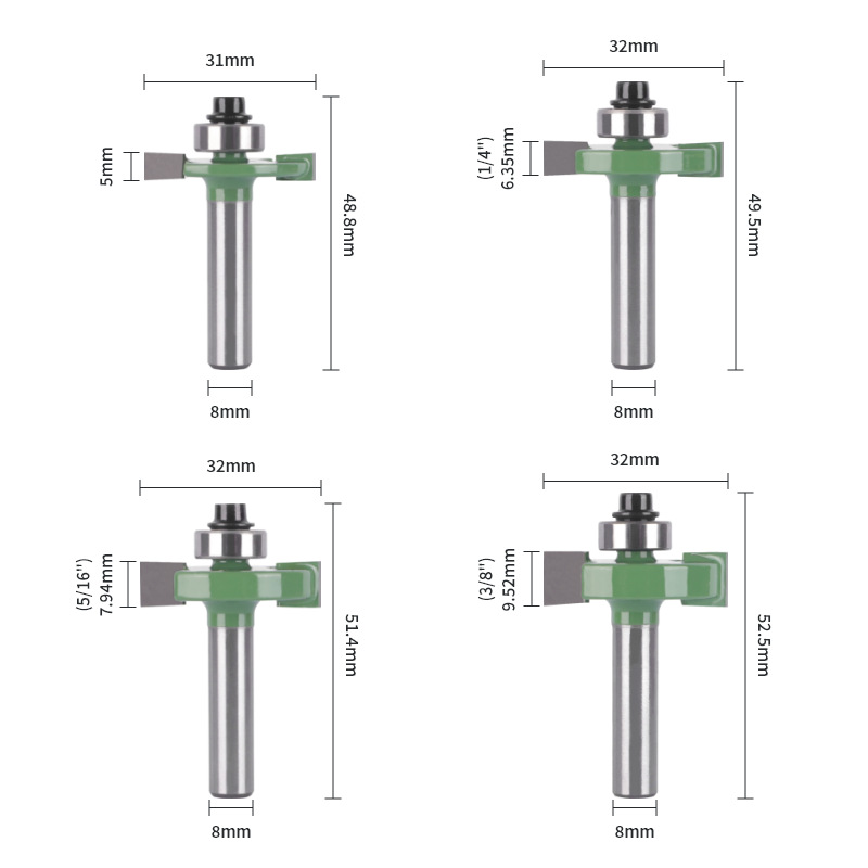
The ball bearing T-slot cutter is a precision woodworking tool built for one-pass T-slot grooving and edge trimming. Ordinary grooving cutters need repeated setup and several passes. That often causes uneven groove depth, offset positions and edge chipping. This cutter uses a front ball bearing for automatic positioning. It keeps groove depth and walls uniform with neat results. Browse our full range of T-Type Router Bits to see how the design removes manual alignment and lifts both efficiency and finish quality.
1. Professional Structure and Material Specifications of Ball Bearing T-Slot Cutters
Strong performance comes from a scientific structure and quality materials. The tool splits into four core parts. Each part uses standard material and angle settings to balance smooth cutting, chip flow and tool life.
1.1 Core Structural Composition
Each standard cutter has a shank, cutter body, precision ball bearing and integrated cutting edges. The parts work together with clear roles:
- Shank: The clamping part fits CNC engravers, electric wood routers and trimmers. Its standard cylindrical shape keeps clamping stable and concentric with the spindle, avoiding vibration at high speed.
- Cutter Body: A disc-shaped support that bears cutting pressure and holds the cutting edges and bearing in place.
- Ball Bearing: Mounted at the front as a profiling guide. It hugs the workpiece edge or fence, locks cutting position and depth, and removes the need for repeated manual calibration.
- T-Shaped Cutting Edges: The working core with horizontal and vertical edges. It forms the flat bottom and vertical walls of the T-slot in one pass.
1.2 Professional Material and Angle Parameters
The blade inclination angle (θ) is held between 3° and 8°. This cuts resistance and load, and pairs with the spiral chip groove to speed chip exit. The body uses 45# steel, quenched and tempered to 40–48 HRC for rigidity and impact resistance. The edges carry tungsten-cobalt carbide for hardness, wear resistance and sharp, long-lasting cuts.
2. Main Application Scenarios
With automatic positioning and one-pass forming, the cutter suits precision grooving and edge trimming on many wood panels. It works on solid wood, plywood, veneer and MDF. Core uses fall into two groups.
2.1 Precision T-Slot Grooving
It cuts standard T-grooves such as concealed handles for cabinet and wardrobe doors, bench fixing slots, and jig or fixture grooves. One-pass forming keeps groove width and depth consistent. Walls stay flat and vertical, meeting assembly standards.
2.2 Edge Trimming and Decorative Grooving
With a fence, the cutter opens neat tenon and decorative grooves on panel edges. The front bearing hugs the edge and limits chipping of veneer and composite surfaces. It solves uneven edges and surface damage seen in older methods, ideal for custom furniture finishing.
3. Standard Tool Installation and Tool Setting Method
Correct clamping and tool setting are the base for stable runs and good parts. Good setup avoids vibration, deviation and safety risks.
Insert the shank into the collet to a sufficient depth. Avoid short overhang from weak clamping, which causes vibration, runout and uneven grooves. After clamping, check concentricity so the cutter spins true with no shake.
For tool setting, use the front bearing. Press it against a standard fence or datum edge, then fine-tune height and position for the target groove depth and width. Lock parameters after a test cut confirms the size. This unifies positioning across a batch.
4. Complete Processing and Operation Steps
The workflow for handheld trimmers and CNC machines is clear and efficient. Follow these steps for steady, high-quality results each time.
Step 1: Fix the workpiece and position the guide fence. Clamp the panel firmly to stop movement during cutting. Place the auxiliary fence tight to the cut side to give the bearing a stable datum.
Step 2: Start the equipment for pre-operation. Power on the router or trimmer and let it idle briefly. Confirm smooth rotation, no odd noise or vibration, and free bearing spin.
Step 3: Feed along the guide direction at a constant speed. Keep the front bearing against the fence and hold that contact. Drive the cutter forward at a steady speed along the panel. The bearing limits the path and the T-slot is cut automatically.
Step 4: Segment processing and continuous forming. After one section, move the work or machine while keeping the bearing on the datum. Continue until the whole groove is formed. Turn off the tool only after the cutter fully leaves the cut.
5. Key Processing Precautions
To extend tool life and keep groove surfaces flat, follow set process and maintenance rules. Pay attention to these points.
5.1 Adopt Climb Milling Priority
Always choose climb milling for grooving. This avoids grain tear-out and edge chipping, improves wall finish and lowers wear for stable long-term use.
5.2 Strengthen Chip Removal and Heat Dissipation
The 3°–8° angle and spiral groove help chip flow, yet deep or closed grooves still trap chips. Use air or vacuum dust control to clear chips in real time. This prevents overheating, blade burning and defects.
5.3 Regular Ball Bearing Maintenance
Bearing rotation sets positioning accuracy. Before each use, check that it spins freely with no jam from dust. Clean the bearing and residue often to avoid dust lock that throws off cutting depth.
5.4 Reasonable Matching of Cutting Parameters
Match spindle and feed speed to panel density and cutter diameter. For hardwood and high-density fibreboard, lower the feed to avoid chipping the carbide. For softwood and low-density boards, keep a steady medium feed to balance speed and quality.
5.5 Stabilize Feeding and Clamping State
Bearing-guided edge work needs steady operation. Feed with even force and a stable path to avoid sudden cutter drift. Keep the bearing on the fence; losing contact changes depth, ruins the panel or causes accidents.
6. Core Advantages of Ball Bearing T-Slot Cutters
Versus ordinary T-slot cutters, the bearing-guided type shows clear gains in accuracy, efficiency and finish. It fits modern batch woodworking well.
6.1 One-Time Integrated Forming
The integrated T-shaped edge cuts the flat bottom and vertical walls together in one pass. It removes repeated feeding and trimming, greatly simplifying the process.
6.2 Stable and Consistent Processing Accuracy
The bearing positions the cut automatically, so depth and position stay uniform. Manual errors drop and consistency rises, ideal for standard batch production.
6.3 Effectively Suppress Plate Chipping
The front bearing presses the panel edge during the cut, limiting veneer and fibre cracking. It protects fragile veneer and composite panels and lifts yield.
6.4 Significantly Improve Production Efficiency
The tool drops repeated setting, calibration and trimming steps. The simpler flow shortens cycle time and raises overall grooving and trimming output.
Conclusion
The ball bearing T-slot cutter is a high-precision, high-efficiency tool for T-slot grooving and edge trimming. Its bearing profiling structure and integrated carbide T-edges solve the low efficiency, poor accuracy and easy chipping of older methods. With sound materials and angle design, it keeps strong cutting and durability on solid wood, composites and decorative panels.
Standard clamping, the right milling direction, real-time chip removal and steady feeding let the tool deliver one-pass forming, accurate positioning and anti-chipping. It is a core tool for custom furniture, woodworking molds and panel finishing. Explore our T-slot router bits to match the right cutter to your groove specs.
FAQ
Q1: What is a ball bearing T-slot cutter used for?
A1: It is mainly used for precision T-slot grooving and plate edge trimming in woodworking, including cabinet door hidden handle grooves, workbench fixing grooves and decorative tenon grooves, suitable for solid wood, plywood and veneer panels.
Q2: What is the advantage of the ball bearing design?
A2: The front ball bearing can fit the guide fence or workpiece edge automatically, realizing accurate positioning without manual calibration, ensuring consistent groove depth and position, and effectively preventing plate edge chipping.
Q3: What milling direction is recommended for T-slot cutting?
A3: Climb milling is strongly recommended. It reduces wood grain tearing, improves groove surface smoothness, and lowers tool wear to extend service life.
Q4: How to maintain a ball bearing T-slot cutter?
A4: Check the flexibility of the ball bearing before use, clean dust and chips regularly, match reasonable speed and feed parameters according to materials, and strengthen chip removal and heat dissipation during deep groove processing.