
Blog
Reasonable Selection of Solid Carbide Helical Wood Router Bits: Types, Comparison and Machining Guidelines

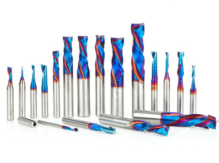
High-speed machining is now the mainstream method in woodworking and furniture production. It shortens cycle times and improves surface finish. Stable performance depends on both precise machines and professional cutting tools. Among all options, the solid carbide helical wood router bit stands out for its stability, long life and adaptability. It is gradually replacing straight-edge cutters in high-precision work.
This guide explains the common types of the solid carbide helical wood router bit, the difference between helical and straight cutters, left-hand and right-hand designs, entry methods, cutting parameters and anti-wear tips. It helps technicians maximize tool life and improve processing quality.

1. Wood Router Bit Basics: Materials, Structures and Common Classifications
Before comparing helical bits, you should master router bit fundamentals. Understanding materials, structure and shape classes helps technicians build a systematic view. It also supports standardized tool matching for efficient wood machining.
1.1 Two Common Router Bit Materials: HSS vs Carbide-Tipped
Woodworking router bits fall into two material types by performance and use: high-speed steel (HSS) and carbide-tipped. They differ clearly in durability, sharpness and application.
Carbide-tipped router bits are known for extreme durability and lasting sharpness. They resist high-temperature wear and impact during high-speed cutting. They are the preferred tool for heavy-duty, long-hour and high-frequency work. In contrast, HSS bits have lower durability and heat resistance. They are more economical for small-batch, low-intensity and temporary projects.
1.2 Basic Router Bit Structure
A standard woodworking router bit has three core parts: shank, body and cutting edges. The shank connects to the spindle and decides clamping stability. The body supports overall rigidity. The cutting edges directly contact and cut the wood.
The shape, count and angle of the edges decide the machining shape, accuracy and technique. This enables precise carving, grooving and trimming. You can explore our full range of carbide insert router bits to compare profiles and shank sizes.
1.3 Common Conventional Router Bit Shapes andamp; Applications
Different bit shapes serve exclusive functions and decorative effects. They cover basic grooving, joint making and edge beautification in daily woodworking.
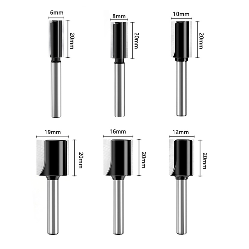
Straight Bits: The most universal tool, with flat bottoms and sharp linear edges. They process standard grooves, dadoes and rabbets, and are widely used in board splicing and plane trimming. They adapt to most basic cutting scenarios.
Rabbeting Bits: Built for standard grooves, channels and notches, with adjustable depth and width. They create tighter mechanical joints than butt joints and improve structural firmness. They are essential for cabinet and furniture frames.
Roundover Bits: These polish sharp edges into smooth rounded contours. They improve aesthetics and remove sharp corners for safety. They are common on desktops, chair arms, drawers and decorative moldings.
Cove Bits: With concave arc profiles, cove bits carve elegant curved lines and grooves. They add artistic layering to flat boards and are used for furniture decoration and door trimming.
Roman Ogee Bits: With classic composite curves, they are mainstream molding tools. They upgrade cabinet facades and build custom high-end decorative edges.
1.4 Specialized Woodworking Router Bits for Precise Machining
For cabinet making, structural splicing and special-shaped work, specialized bits enable standardized, efficient custom machining.
Raised Panel Bits: Designed for cabinet door panels, they create 3D effects and trim back edges. They cut standard 1/4-inch tenons to match frame grooves, ensuring precise assembly.
Dovetail Bits: These machine classic dovetail joints known for strength and durability. They are used in drawers, storage boxes and load-bearing furniture.
Keyhole Bits: With a special-shaped groove, they process keyhole mounting slots. They suit wall shelves, photo frames and hanging decorations.
Edge Forming Bits: They support diverse contours, from simple beads to complex edges. They enrich surface detail in custom wood decoration.
High-speed cutting is widely adopted in furniture manufacturing for efficient material removal and superior quality. The market now offers three mainstream high-performance cutters: integral solid carbide helical wood router bit end mills, clamped shank cutters and PCD brazed shank cutters. Each has exclusive advantages.
As a core high-precision tool, the solid carbide helical wood router bit features an integrated carbide structure and continuous helical edges. It is optimized for high-speed milling, grooving, trimming and special-shaped routing. It delivers more stable force, lower vibration and better finish than other types.
2. Solid Carbide Helical Wood Router Bit vs Straight-Edge Cutters
Structural differences between straight-edge and helical bits create clear gaps in stability, finish and life. These gaps decide the suitable materials and working conditions.
Traditional straight-edge bits use full-edge synchronous cutting. The whole edge contacts and leaves the workpiece at the same time. This creates a large contact area and intense friction. Long runs easily cause edge wear, burrs and uneven surfaces. Therefore, straight-edge cutters suit only low-demand soft wood with simple structures.
In contrast, helical bits use a staggered spiral edge. The contact point changes dynamically as the tool rotates. This disperses instantaneous resistance, reduces vibration and realizes gradual shear cutting. The solid carbide helical wood router bit can process both soft and hard wood steadily. Even at maximum feed speed, it keeps a smooth, clean surface. Uniform stress also slows fatigue wear, giving a much longer life.
3. Characteristics of Left-Hand and Right-Hand Helical Router Bits
By helix direction and chip discharge, the solid carbide helical wood router bit divides into right-hand, left-hand and composite types. Each has unique mechanics and scenarios. Correct selection avoids defects and improves stability.
3.1 Right-Hand Helical Router Bits
Right-hand bits cut right and spiral right, pushing chips upward along the groove. This excels in groove milling and confined spaces with poor natural chip removal. However, the upward force can lift the workpiece, causing warping or displacement. Increase clamping force, improve fixtures or use segmented cutting to solve this.
Vertical plunge cutting is mechanically possible but risks edge chipping from concentrated stress. Oblique entry is the standard method. It gradually increases axial depth and grows milling force slowly, reducing impact on tool and spindle.
3.2 Left-Hand Helical Router Bits
Left-hand bits cut right but spiral left, discharging chips downward from the bottom. The downward pressure compresses and fixes the workpiece, ensuring a smooth, burr-free top surface. However, the bottom may show rough burrs from downward friction. Hidden grooves can also cause bottom chip blockage.
For better stability, pre-cut the workpiece before edge trimming with left-hand bits. Notably, left-hand bits are not suitable for vertical plunge cutting. Concentrated axial stress would cause tool breakage or severe clogging.
3.3 Composite Helical Router Bits
Composite bits integrate upper and lower spiral edges on one body. The dual structure compresses and cuts both surfaces, offsetting unilateral stress. It avoids burrs, chipping and floating on both faces. It achieves double-sided finishing in one pass, ideal for high-standard panel and composite board work.
4. Selection of Standard Helical Router Bit Machining Methods
Entry modes directly affect tool loss, accuracy and finish. Choose feeding trajectories by shape to avoid damage and improve efficiency.
Vertical Direct Plunging: Direct downward feeding causes instantaneous impact on the edge, leading to chipping and damage. It is not recommended for helical bits.
Edge Step Feeding: A two-stage method that keeps the tool away during descent and uses lateral feeding for contact. It avoids vertical impact and protects the edge. It suits edge trimming and plane milling.
Slant Trajectory Feeding: Gradually increases axial depth to the preset value, growing milling force steadily. The gentle change reduces impact and lowers chipping risk. It fits most conventional grooving.
Spiral Plunging Feeding: The tool cuts downward in a continuous spiral from above. The stable speed and stress ensure accuracy. It supports high-speed work and is optimal for irregular contours and 3D cavities.
5. Scientific Selection of Cutting Parameters
Spindle speed and feed rate are the two core parameters for efficiency and tool life. Match them to equipment and material for balanced performance.
For mainstream CNC machines, the spindle speed range is 10,000 to 40,000 r/min. Higher speed gives a smoother surface within a range. However, excessive speed intensifies friction, generates heat and accelerates wear and edge passivation.
Feed rate cannot use fixed values. It depends on machine precision, spindle power, clamping stability and workpiece fastening. Adjust parameters on site to avoid overload or low efficiency.
6. Practical Strategies to Reduce Carbide Tool Wear
Main wear forms include brittle fracture and plastic deformation. Carbide is sintered by powder metallurgy with microscopic defects inside. Long alternating impact causes fatigue damage. Standardized operation and maintenance delay wear and extend life.
First, keep the holder clean before installation for complete fitting and high precision. Second, prioritize high-rigidity tools with larger diameter or shank to improve impact resistance. Third, minimize overhang to reduce cantilever vibration and stress.
Fourth, run new tools at 50% speed for a break-in period to polish the edge and stabilize performance. Fifth, use climb milling for roughing to cut resistance and edge wear. Sixth, monitor status and lower speed and feed when vibration grows. For the complete carbide cutter catalog, visit carbide-tipped router bit cutters.
Conclusion
The solid carbide helical wood router bit is a core high-efficiency tool for modern high-speed wood processing. Different from straight-edge cutters, it offers stable performance and long life. Different helix types and feeding modes expand its adaptability.
Technicians should select right-hand, left-hand or composite helical bits by material and requirement. They should match standardized trajectories and reasonable parameters. Standardized installation, break-in and dynamic adjustment reduce wear and stabilize accuracy. This realizes high-efficiency, high-quality and low-consumption woodworking.
FAQ
Why are helical router bits better than straight-edge bits?
Helical bits use staggered gradual cutting to disperse friction and impact. They deliver smoother finish, lower vibration and longer life. They suit hard wood and high-speed work, while straight bits suit only soft, low-demand processing.
What is the difference between left-hand and right-hand helical bits?
Right-hand bits discharge chips upward for smooth grooving but may lift workpieces. Left-hand bits discharge chips downward to compress workpieces with smooth tops. Composite bits realize double-sided burr-free cutting.
Which entry method is best for high-speed wood milling?
Spiral plunging and slant trajectory feeding are optimal. They change stress gently, avoid edge chipping and support high-speed work. They suit irregular and 3D cavity processing.
How to effectively reduce carbide helical tool wear?
Key measures include precise clean installation, short overhang, low-speed break-in, climb milling for roughing and timely parameter adjustment when vibration increases.